Discover Our Projects
Explore Our Innovative Projects
At MinePower, we pride ourselves on executing cutting-edge projects that push the boundaries of innovation. Browse through our featured work and see how we turn big ideas into tangible results.
- By minepowerindia@gmail.com
- March 2, 2026
PLC/HMI IP Address Configuration
How to Set IP Address in PLC and HMI Caption: PLC/HMI IP Address Configuration In modern industrial automation systems, communication...
- By minepowerindia@gmail.com
- February 12, 2026
Hands-on Training
Caption: Hands-on Training In today’s industry-driven world, hands-on training is essential for students to convert classroom knowledge into real engineering...
- By minepowerindia@gmail.com
- January 31, 2026
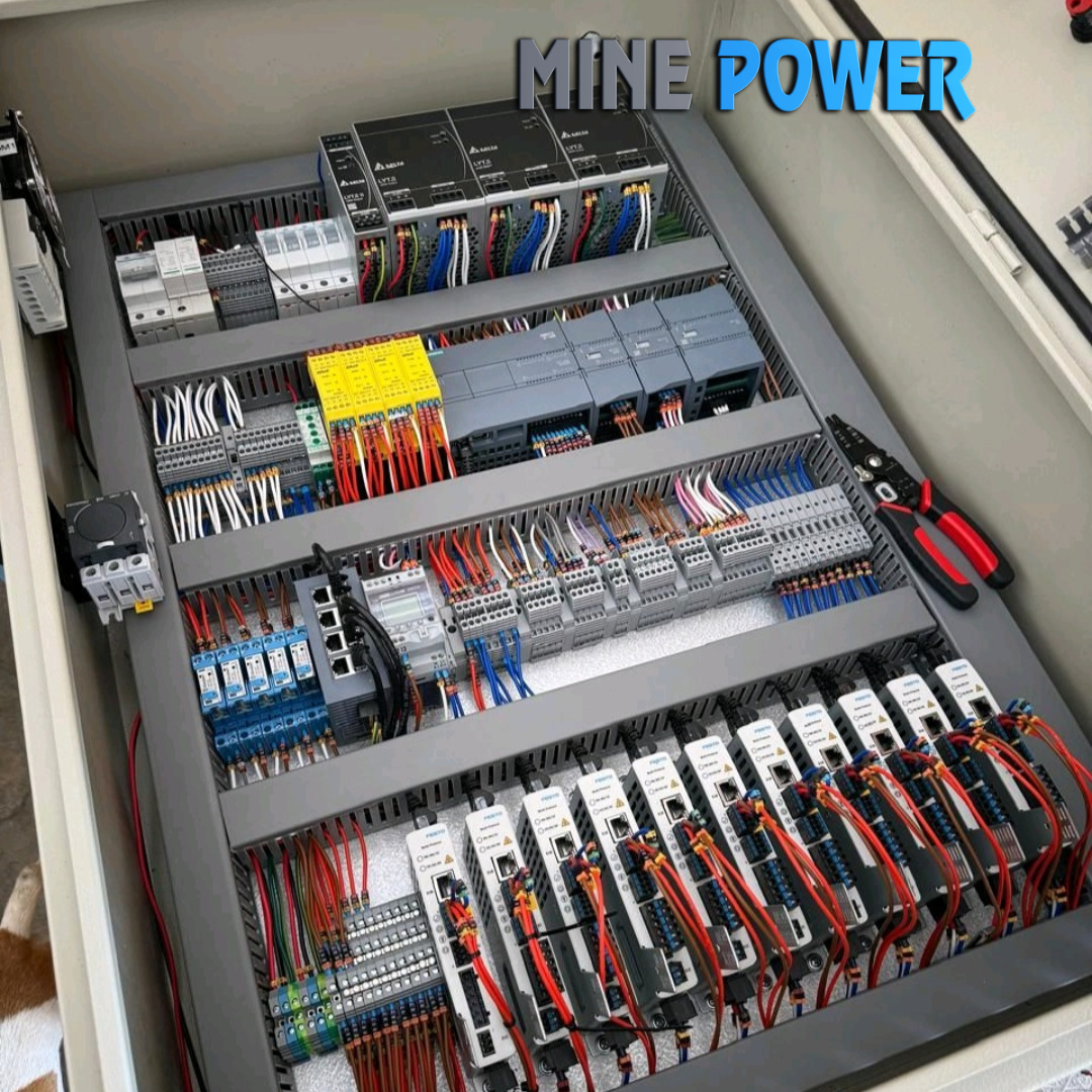
Types of I/O Modules in Industrial Automation
Types of I/O Modules in Industrial Automation 1. Digital Input (DI) Modules Digital input modules read ON/OFF signals from field...
- By minepowerindia@gmail.com
- January 28, 2026
SCADA Alarms—How They Help Avoid Machine Failures
SCADA Alarms—How They Help Avoid Machine Failures (Understanding the Alarm Window in Industrial Automation) In modern industrial environments, unexpected machine...
- By minepowerindia@gmail.com
- January 8, 2026
PLC Programming: The Backbone of Modern Industrial Automation
In today’s fast-moving industrial world, PLC (Programmable Logic Controller) programming has become one of the most essential skills for automation...
- By minepowerindia@gmail.com
- September 14, 2025
MCU vs PLC: Rivals or Partners in the Future of Automation?
MCU vs PLC: Rivals or Partners in the Future of Automation? A smartwatch is powered by one. The other powers...
- By minepowerindia@gmail.com
- September 7, 2025
Microcontroller vs PLC: Which One Powers the Future of Automation?
Microcontroller vs PLC: Which One Powers the Future of Automation? If you’ve ever wondered why your washing machine runs smoothly...
- By minepowerindia@gmail.com
- September 1, 2025
How PLCs Are Programmed
PLC Programming and Ladder Logic: A Deep Dive into Industrial Automation Introduction: Why PLC Programming and Ladder Logic Matter PLC...
- By minepowerindia@gmail.com
- August 23, 2025
PLC: The Hidden Brains of Modern Industry
The Hidden Brains of Modern Industry: At Mine Power, we believe automation is the foundation of modern manufacturing. Behind every...
- By minepowerindia@gmail.com
- June 16, 2025
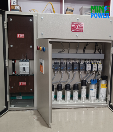
Why Electrical Panels Are Necessary
1. Essential for Power Distribution Without an electrical panel, there is no structured way to distribute electricity from the main...
- By minepowerindia@gmail.com
- June 16, 2025
Importance of Electrical Panels in Industries & Buildings
1. Central Power Distribution Electrical panels act as the control hub that distributes electricity from the main supply to various...
- By minepowerindia@gmail.com
- August 11, 2024
Project Update : Natural Gas Control System
Natural Gas Control System for Craftsman Automation At Mine Power, we specialize in designing and executing industrial automation and gas...
- By minepowerindia@gmail.com
- August 11, 2024
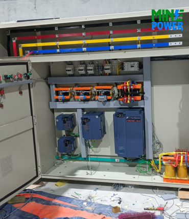
Project Update : 560 kW VFD Drive Panels for Salem Water Board
560 kW VFD Drive Panels for Salem Water Board Mine Power specializes in delivering high-capacity VFD panels, PLC automation, and...
- By minepowerindia@gmail.com
- August 11, 2024
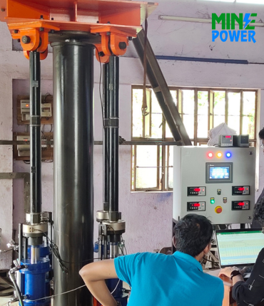
Hydraulic Load Testing Equipment for Skyroot Aerospace
Hydraulic Load Testing Equipment for Skyroot Aerospace At Mine Power, we take pride in delivering high-precision engineering solutions that meet...
- By minepowerindia@gmail.com
- August 11, 2024
Auto Batching Plant for Fly Ash Bricks
🧱 Auto Batching Plant for Fly Ash Bricks At Mine Power, we specialize in delivering smart automation solutions that enhance...
- By minepowerindia@gmail.com
- August 9, 2024
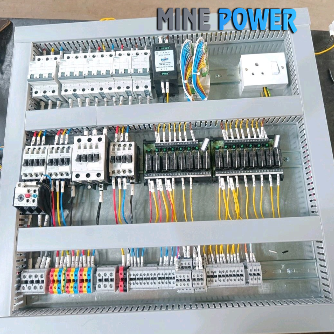
Textile Cloth Winding Machine Panel
🧵 Project Spotlight: Textile Cloth Winding Machine Panel At Mine Power, we bring automation and control to the heart of...
- By minepowerindia@gmail.com
- August 9, 2024
1600-Ton Hydraulic Press Control Panel
1600-Ton Hydraulic Press Control Panel At Mine Power, we empower industrial machinery with smart control systems that bring precision, safety,...
- By minepowerindia@gmail.com
- August 9, 2024
How Panels Are Made in Industries: Step-by-Step
1. Requirement Analysis & Design Client requirements, load data, and applications are studied. Engineers design panel layouts using CAD software...

Mine Power is a leading Electrical automation solutions provider, serving diverse industries with a skilled team of engineers boasting over 10 years of experience.