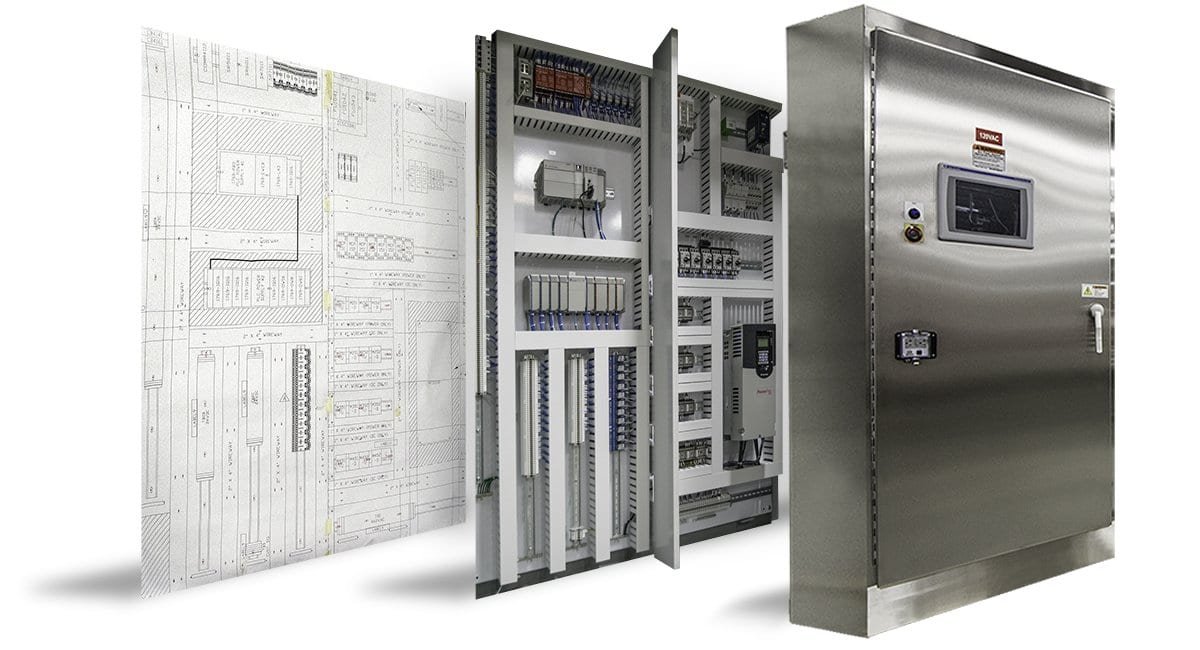
1. Requirement Analysis & Design
-
Client requirements, load data, and applications are studied.
-
Engineers design panel layouts using CAD software (like AutoCAD Electrical or EPLAN).
-
Component selection (MCBs, MCCBs, contactors, relays, PLCs, VFDs) is finalized.
2. Material Procurement
-
Enclosures (MS/SS/Aluminum), busbars (Copper/Aluminum), switchgears, terminals, wiring accessories, etc., are sourced.
-
All materials are quality checked upon receipt.
3. Fabrication & Painting
-
The panel enclosure is fabricated by cutting, bending, and welding metal sheets.
-
Holes are made for components, cable entry, ventilation, etc.
-
Then it’s powder-coated or painted for corrosion resistance and proper finish.
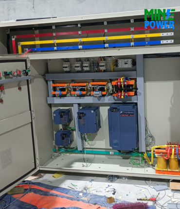
4. Busbar Assembly
-
Busbars are cut, drilled, and mounted as per the design.
-
Heat-shrink sleeves or color codes are applied (R-Y-B and neutral/earth).
-
Insulation, spacing, and support clamps are ensured as per IS/IEC standards.
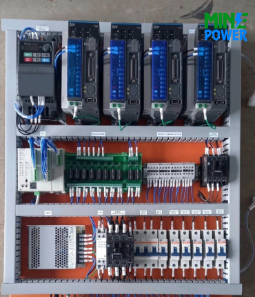
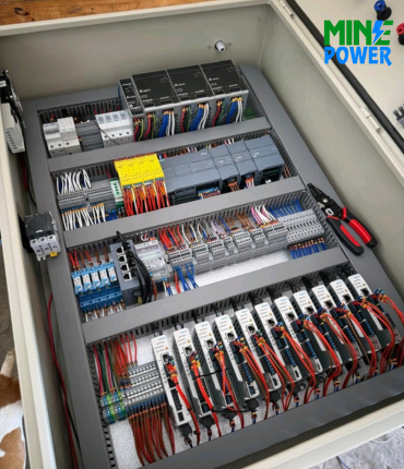
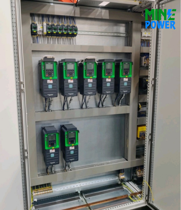
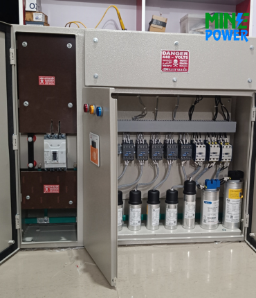
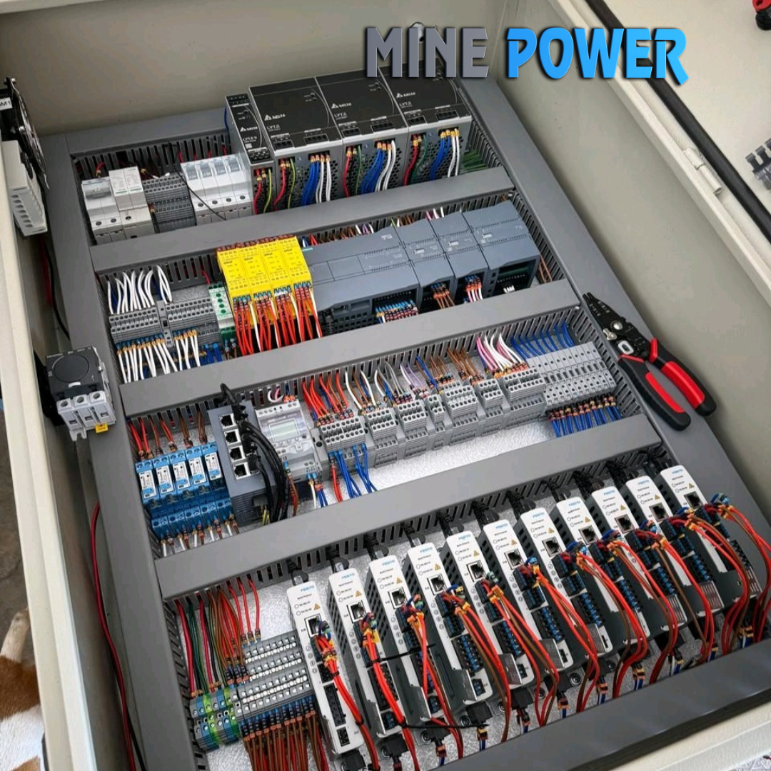
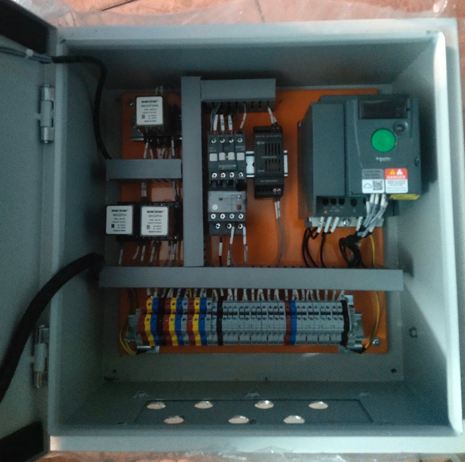
5. Component Mounting
-
All electrical components (breakers, relays, meters, VFDs, and PLCs) are fixed on mounting plates or DIN rails.
-
Proper spacing and alignment are maintained for safety and maintenance.
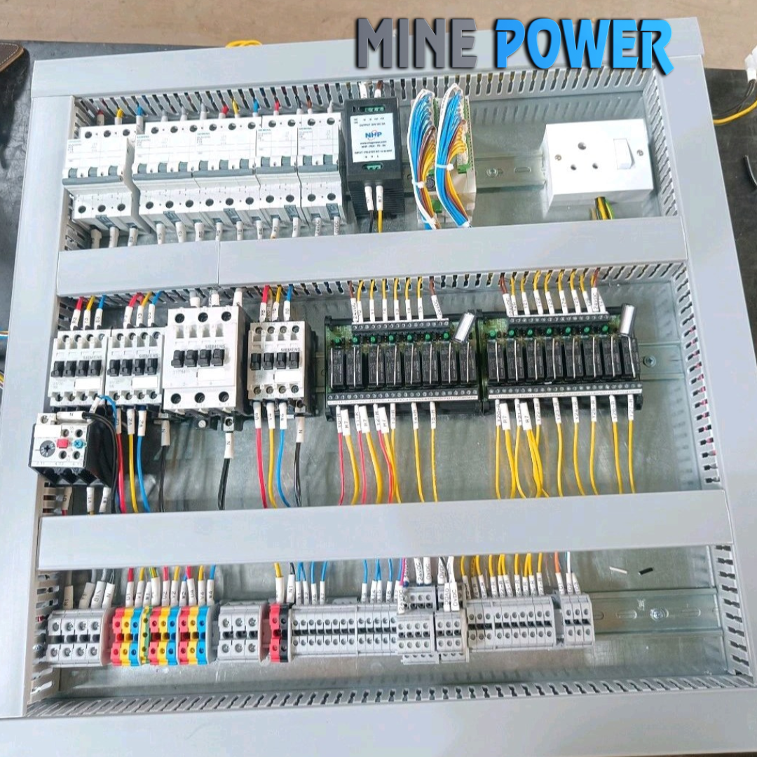
6. Internal Wiring
-
Control and power wiring is done using color-coded wires.
-
Ferrules, cable tags, lugs, and sleeves are applied for identification.
-
Wiring is routed neatly through cable ducts.
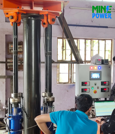
7. Testing & Quality Check
-
High-voltage (Hi-pot), insulation resistance (IR), and continuity tests are performed.
-
Control logic is tested if PLC/automation is involved.
-
The panel is energized to check functionality, safety, and tripping features.
8. Labeling & Documentation
-
Component labeling, terminal tags, panel nameplates, and schematic drawings are added.
-
A user manual with wiring diagrams is prepared.
9. Final Inspection & Dispatch
-
Final QA is done.
-
The panel is packed securely and dispatched to the site for installation.